Circuit Protection & Cable Selection
PLEASE NOTE: The advice we provide below is guidance only. If you are unsure, please consult a qualified electrician.
Planning your circuit(s)
When looking to wire up and power appliances in your vehicle yourself, it’s important to take the time to plan what you want to power and how you wish to go about it.
The first step is to check how much current (measured in Amps) will be going through the circuit(s). To figure this out, check the current requirements (sometimes referred to as amperage) of each appliance you will be powering on each circuit. How much current does it draw? Is there a start-up current figure listed?
You can normally find this in the appliance manual or an a sticker or plate on the appliance itself.
Having difficulty finding the amperage of an appliance? Sometimes the amperage of an appliance is not listed on the appliance itself, more commonly you get the wattage and voltage of the appliance, in which case you should divide the wattage by the voltage, e.g., For an appliance which uses 100 Watts on a 12V circuit, the amperage is equal to 100÷12 which is 8.3 Amps.
Protecting your circuit
Once you’ve figured out how many circuits you’ll be working with and how much current each of them will use, you’ll need to sort some protection for each circuit. Circuit protection refers to intentionally including a weak link in your circuit. This is a necessity to prevent damage to your circuit or appliances in the event of an electrical fault such as a short circuit or circuit overload.
For 12V circuits, you’ll most likely use a 12 volt fuse. For mains circuits, you’ll need a circuit breaker, and this will normally be either a MCB (Miniature Circuit Breaker) or RCBO (Residual Current Breaker with Over-current). Choose one with a rating which is a little above the current required in your circuit.
Selecting Cable type
Mains (230V) and 12 volt circuits require different types of cable. Cable to be used in mains circuits will usually have 3 conductors (cores). Cables for use in 12 Volt circuits will often have just 1 or 2 conductors although there are cables with more conductors which are used for specific purposes such as 13 core cable used on caravan towbars.
It’s very important that the correct type of cable is used in each circuit so make sure to choose a cable which is right for the type of circuit you are wiring.
- Browse of range of cable for 12 volt circuits
- Browse our cables for mains (230V) circuits
Selecting the correct cable size
Now that you’ve chosen the circuit protection and cable type you need, choosing the right size of cable is the next step. Cables come in a range of sizes, measured in mm2 and the general rule of thumb is that the larger the cable diameter, the more current it can have running through it before it becomes overloaded. However, the amount of current each cable can carry will also vary depending on:
- How the cable is fixed.
- How many cables are grouped together.
- The ambient temperature.
Fixing Methods Explained:
Considering the fixing method you’ll be using is very important when choosing electrical cables - depending on where they are placed in your vehicle, the heat generated as current flows through the cable will be able to escape in different amounts, e.g., a cable in protective tubing in a thermally insulated wall (method A) will be able to get rid of less heat than a cable clipped directly onto the wall of a caravan or motorhome (method C) because there is less free space for that heat to escape into. As a result, you will be able to put less current through a cable using method A than method C before it overheats, which in turn causes damage to the cable, reducing the lifespan of the cable and in extreme cases, potentially posing a fire risk.
In the specification table provided for each cable listed on our site, you’ll find the amount of current each type of cable can safely carry depending on how it is fitted in your vehicle. Read the explanations below to find the fixing method that corresponds to how you are installing cable in your vehicle, then select a cable which is big enough so that it has a larger current capacity than your protective device.
- Fixing Method A – “Cables in conduit in a thermally insulated wall” – This refers to a cable within some sort of protective metal or plastic tubing fixed within an insulated wall of your vehicle.
- Fixing Method B – “Cables in conduit on a wooden or masonry wall” – This refers to a cable within some sort of protective metal or plastic tubing that is mounted onto a wooden or masonry wall within your vehicle.
- Fixing Method C – “Cable on a wooden or masonry wall” – This refers to cable being clipped directly onto a wooden or masonry wall with no protective tubing.

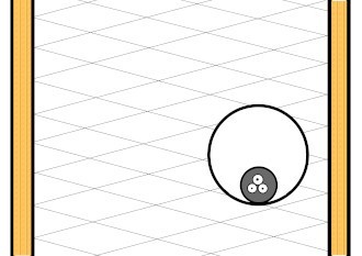
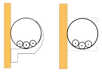
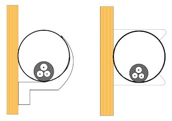
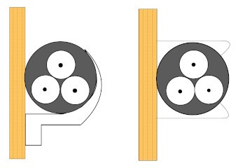
The figure we provide in the specification table is the maximum amount of current you can put through the cable in each setting, so make sure your expected current is below this so you have some headroom in case of potential electrical surges.
Current carrying capacities we provide are taken from BS7671 IET Wiring Regulations – 18th Edition. Ratings for single core cables are from table 4D1A and multicore cables are taken from table 4D2A.
Multiple cables grouped together:
The ratings we provide in the specification table on the listing for each cable we sell are based on an individual single core or multi-core cable. It is important to mention that once you start grouping cables together, the current carrying capacity of each cable will start to decrease for the same reason as above; there will be less room for heat to escape from each cable.
To work out the decreased current carrying capacity if you are grouping cables together, multiply the amperage rating of a single cable using your desired fixing method, by the figure in the table below that corresponds with the number of cables you plan to group together.
(Table 4C1 pg396 BS7671 18TH Ed.)| # of cables | Correction Factor |
|---|---|
| 1 | 1.00 |
| 2 | 0.80 |
| 3 | 0.70 |
| 4 | 0.65 |
| 5 | 0.60 |
| 6 | 0.57 |
| 7 | 0.54 |
| 8 | 0.52 |
| 9 | 0.50 |
| 12 | 0.45 |
| 16 | 0.41 | 20 | 0.38 |
If the carrying capacity of the cable you selected is now below the capacity of your protective device, you will need to select a larger cable.
Ambient Temperature:
Another factor to consider when choosing electrical cable is the ambient temperature of wherever you will be using the circuit. 30°C is the control figure at which most cable ratings (including the ones we’ve listed) are taken and once the ambient temperature goes above this, the current carrying capacity of the cable will start to decrease because – you guessed it – the cable will not be able to get rid of as much heat!
To figure out how much the rating of the cable will decrease, multiply the rating of the single cable using your desired fixing method by the figure in the table below that corresponds with the ambient temperature you’re likely to be operating the circuit in.
(Table 4B1 pg394 BS7671 18th Ed.)| Ambient Temperature °C | Correction Factor |
|---|---|
| 25 | 1.03 |
| 30 | 1.00 |
| 35 | 0.94 |
| 40 | 0.87 |
| 45 | 0.79 |
| 50 | 0.71 |
| 55 | 0.61 |
| 60 | 0.50 |
If the carrying capacity of the cable you selected is now below the capacity of your protective device, you will need to select a larger cable.
Applying multiple correction factors
When applying multiple correction factors to the current rating of your desired cable, the factors compound.
Let's use an example - there's a cable fixed in a vehicle with a current carrying capacity of 13 Amps. We will group 3 of them together and assume that the ambient temperature the circuit is operating in is 40°C.
First, we find the correction factor for grouping 3 of these cables together, which by looking at the relevant table above is 0.70. Then we multiply our cable rating by this:
- 13 x 0.70 = 9.1 Amps
Next, we use the table above to find the correction factor for the ambient temperature, which in this instance is 0.87 and multiply our new rating figure of 9.1 Amps by this:
- 9.1 x 0.87 = 7.9 Amps
So, in this example, the actual current carrying capacity is actually 7.9 Amps, down 40% from the initial rating of 13 Amps.
Voltage Drop:
Once you have selected the appropriate cable for your needs and you know the length of cable you will require, you should check the expected voltage drop to ensure the circuit will work as planned. Voltage drop is the process by which some voltage is lost as the current travels along a length of cable from your power source to the appliance.
- Voltage drop on mains (230V) circuits should be kept to a maximum of 3% for lighting circuits (6.9V) and 5% for all other circuits (11.5V).*
- We recommend voltage drop on all 12 Volt circuits should not exceed 5%. **
* Taken from BS7671 IET Wiring regulations – 18th Edition Table 4Ab
** BS EN 1648 suggests a voltage drop of 0.8V (6.7%) is permissible for 12 volt circuits in caravans and motorhomes. However, we recommend sticking to a maximum of 0.6V (5%) in line with Section 715.525 of BS 7671
You can calculate voltage drop using the formula below:
Cable voltage drop rating (see spec table for cable) X Current (Amps) in circuit X Cable length in metres
This formula will give you a figure in millivolts, so you divide this figure by 1000 to get the amount in volts.
Calculate the voltage drop for your circuit and make sure it is within the limits described above. If it is not you may be able to re-route your cable to make the circuit shorter. If not, you will need to use a use a larger diameter cable.
Cable rating vs protective device rating:
Once you have calculated the amp rating of the cable you’ll be using, compare this to the rating of your circuit protection device; the rating of your cable must be higher than that of the protective device so that, if there is an electrical fault, the fuse will blow before damage can be done to the cables.
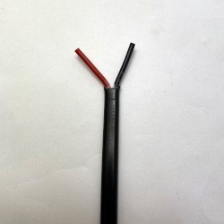
2 Core twin flat black cable with 1.0mm2 conductor and black and red core.
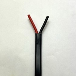
2 Core twin flat black cable with 2.5m2 conductor and black and red core.
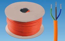
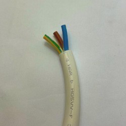
3 Core round flex mains cable with orange sheath and 3183Y core colours and 2.5mm2 stranded conductor.
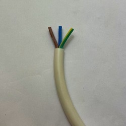
3 Core round flex mains cable with white sheath, 3183Y core colours and 1.5mm2 stranded conductors.
3 Core round flex mains cable with White sheath and 3183Y core colours and 2.5mm2 stranded conductor.
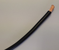
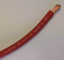
Single core PVC sheath cable with 25mm2 conductor area. Ideal for main battery connection or welding cable use.
Single core PVC sheath cable with 25mm2 conductor area. Ideal for main battery connection or welding cable use.
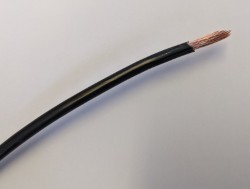
Single core, multi-strand electrical cable with black outer insulator suitable for use in caravan, motorhome and boat 12 volt systems as well as cars and the 24 volt systems in trucks. 6mm2 conductor area is suitable for currents up to maximum 50Amp.
Single core, multi-strand electrical cable with red outer insulator suitable for use in caravan, motorhome and boat 12 volt systems as well as cars and the 24 volt systems in trucks. 6mm2 conductor area is suitable for currents up to maximum 50Amp.

